Component Connectivity Example
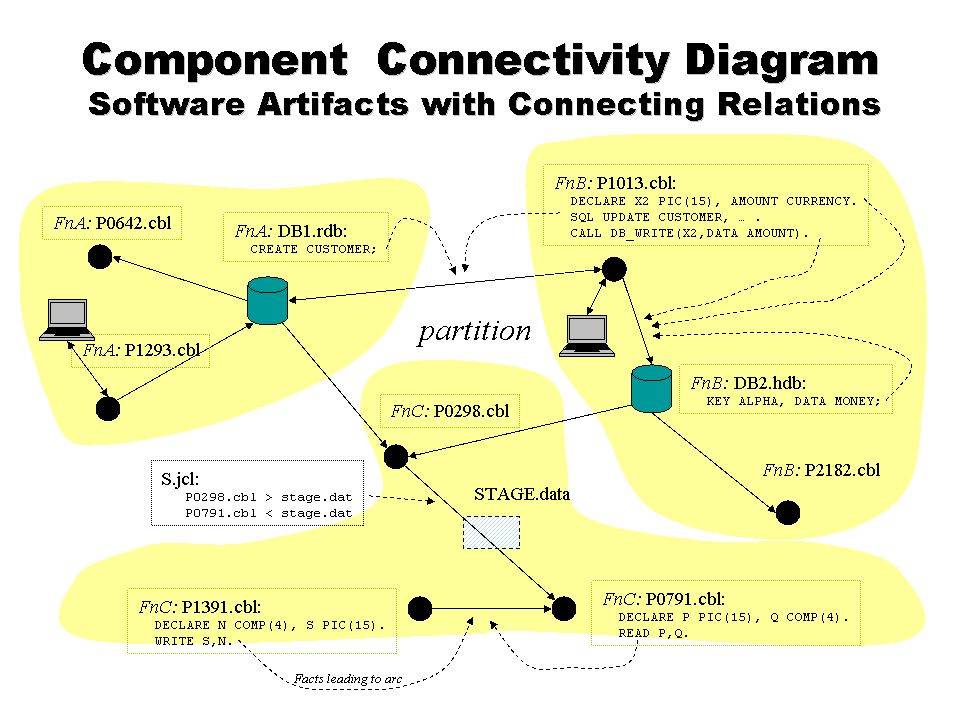
Consider the figure below, which illustrates a set of system components and their
interconnections. The components include COBOL programs (.cbl),
databases (.rdb, .hdb), temporary
files (STAGE.data), and JCL files (.jcl).
The highlighted pseudo-code fragments provide the information showing how one component is related to another.
For example, the file P1013.cbl contains declarations of
X2 and CURRENCY and then contains
a call that writes these values to a database identified as DB2.hdb
(depicted as a black arrow from the P1013.cbl program node and
and the DB2.hdb database node.

Relations are collected as factual evidence (e.g., the evidence in the set of named components provably indicates
the fact) or as heuristic evidence. The arc from P1391.cbl
to P0791.cbl illustrates one heuristic inference that could conceivably be
drawn (although the relationship is too tenuous for the connectivity tool to
justify). Here, no concrete
relationship between the WRITE in P1391.cbl
and the READ in P0791.cbl
can be known because the data file that stages these reads and writes is not apparent.
However, the matching types in the related data declarations and the unknown
aspects of the files that are written and read suggests that such
a relationship cannot be completely ruled out.
After running the COBOL and JCL scanners over this system, the Component Connectivity Tool produces a report whose top page is an index into more detailed reports of each of the related components. You can browse these reports to see how they relate to the system diagram with which we introduced this discussion.
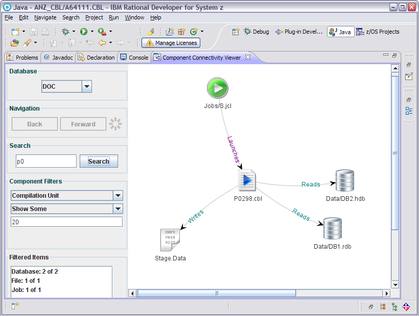
An IBM RDZ Eclipse plugin is available that can show the component connectivity graphically. The example below captures the information from the conceptual diagram above. It is worth remembering that real systems to which this is applied have tens of thousands of components, so you really don't want to see the entire graph at once.

